
Power Bank Engineering Guide
A system-level guide to power bank engineering decisions across cell/PACK, PCB power path, USB PD/PPS, built-in cables, DC-DC efficiency, thermal design and mechanical integration.
Read the power bank as one electrical and mechanical system.
Cell selection, charging protocol, PCB power path, cable loss, thermal behavior and enclosure stack-up interact. A change in one area can force revalidation elsewhere.
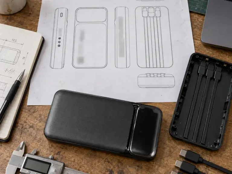
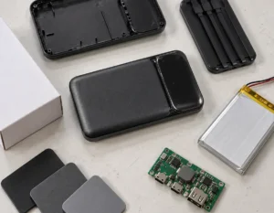
Power Bank Engineering Layers
Cell / PACKenergy · protectionPCB / DC-DC
conversion · heatPD/PPS & Cables
profiles · lossMechanical / Thermal
fit · heat path
Engineering Workflow
Requirements → architecture → validation → release.
01 · Definedevice · power02 · Architect
PACK · PCB03 · Validate
charging · thermal04 · Release
BOM · NPI

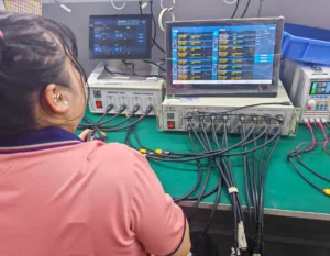
Read Specs as a System
Usable energy depends on efficiency; sustained power depends on PCB, cable and thermal limits; PD/PPS requires controller, port, cable and device compatibility.
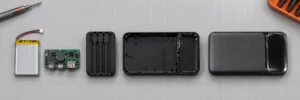
Engineering Decisions Before Validation
Energy BasisCapacity, Wh and usable output establish the real energy target. Power Path
Cell current, DC-DC, PCB, ports and cables must support the required sustained output together. Mechanical / Thermal
Structure, clearances and heat paths determine whether the electrical design remains stable in the final enclosure. Release State
BOM, firmware, interfaces and approved revision must be frozen before pilot build.
Validate the Complete System
Check usable energy, charging profiles, sustained output, cable loss, thermal behavior, mechanical fit and the released BOM/revision as one system.
Validation & NPI → · Factory & Quality →

Magnetic Alignment, Wireless Power and Qi2 Are Separate Engineering Decisions
Review magnet position, charging-coil alignment, phone-case thickness, thermal behavior and wired power together. A magnetic ring alone does not establish Qi2 support or certification.
Magnetic Power Banks → · Qi2 Buyer Checklist → · Product Design & Platforms →
Power Bank Engineering FAQ
Why is usable power-bank capacity lower than rated mAh?
Cell voltage and conversion losses reduce the energy delivered at USB output. Compare Wh, usable energy and efficiency—not mAh alone. Capacity reference →
What determines sustained 20W, 30W or 45W output?
Cell current, DC-DC design, MOSFETs, inductors, PCB copper, connectors, cable loss and thermal limits all matter. High-Power PD platforms →
What does USB PD / PPS support actually mean?
Controller, port, cable and device must support the required profile. PPS also depends on the programmable range and implementation. USB-IF reference →
What should be validated before mass production?
Check capacity, real output, protocols, thermal behavior, cable loss, protection, connector durability, mechanical fit, pilot feedback and the released BOM. Validation & NPI →
Additional Power Bank Engineering FAQ
Why should Wh be reviewed together with mAh?
mAh depends on the cell voltage basis, while Wh expresses stored energy. Comparing Wh gives a clearer basis for capacity and helps avoid misleading comparisons between different cell-voltage systems.
What causes voltage drop in a built-in cable?
Cable resistance, conductor size, connector resistance, length and current all contribute to voltage drop. Higher current makes cable losses more important, so the cable must be validated at the intended charging power.
Why does thermal performance matter even when peak wattage is correct?
A product may reach the advertised wattage briefly but reduce output when heat builds up. Sustained charging performance depends on cell current, conversion efficiency, PCB design, enclosure heat paths and ambient conditions.
What should be checked in a USB-C PD profile review?
Check supported PDOs, PPS ranges when required, maximum voltage and current, port and cable capability, device negotiation and the behavior of other outputs when several ports or cables are used.
How do PCB copper and power-path design affect charging performance?
Copper width and thickness, MOSFETs, inductors, connectors and layout resistance affect efficiency, voltage drop and heat. The power path must be designed for the intended current rather than only the controller's headline capability.
Why should engineering changes be tied to a BOM revision?
A BOM revision identifies the exact cells, PCB, components, cables and materials used in a product version. Linking engineering changes to revisions makes validation, traceability and production control more reliable.
Explore the Other Guide Topics
Private Mold & ODM · Buyer & Sourcing · Quality & Compliance · Product Design & Platform Decisions
Need an Engineering Review for a Power Bank Platform?
Send the target capacity, power, interfaces, cable architecture and enclosure constraints. ZEROSET can map the brief to a current platform and identify the engineering items that need validation.