
Power Bank Built-In Cable Loss & Selection Reference
An engineering reference for built-in power bank cables covering conductor resistance, connector loss, current capability, voltage drop, cable length, mechanical life and validation under real charging loads.
A built-in cable is part of the power path, not only a convenience feature.
Conductor size, connector quality, length, bending life and heat all influence delivered voltage and current. Cable selection should be validated with the actual charging profile and enclosure architecture.
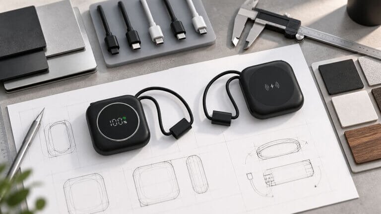
Quick Engineering Review
Review the cable as part of both the power path and the mechanical system.
Electrical LossMeasure resistance and voltage drop at the intended load and cable length.Connector Temperature
Check contacts and connector hotspots under sustained load.Protocol Support
Verify PD/PPS or other charging behavior with the production-intent cable.Mechanical Durability
Validate strain relief, bend path, pull stress and retractable movement.
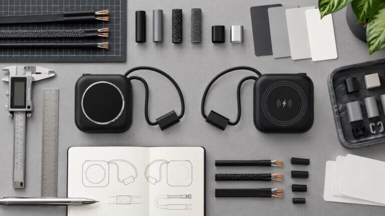
Buyer Decision Points
Electrical PathConductor capability, total resistance and voltage drop determine how much power reaches the device.Connector & Contact
Contact resistance and connector temperature must be checked at sustained load.Protocol & Charging
Confirm the production cable supports the charging profile claimed for the SKU.Strain Relief & Mechanism
Review bend radius, pull stress, fixed-cable support and retractable movement.

Related Engineering
PD & PPS Charging →
Thermal & DC-DC Efficiency →
Mechanical Stack-Up & DFM →
Built-In Cable Platforms →
Retractable Cable Platforms →

Built-In Cable FAQ
Can a cable limit output even if the PCB supports the wattage?
Yes. Cable resistance, connector loss and protocol capability can reduce delivered power or create heat.Does a retractable cable need different validation?
Yes. The movement path, winding mechanism, repeated extension and strain points add mechanical requirements beyond a fixed cable.Should cable revisions be frozen with the SKU?
Yes. Electrical and mechanical performance should stay tied to the approved cable and mechanism revision.Additional Built-In Cable Selection FAQ
What determines voltage drop in a built-in power-bank cable?
Conductor resistance, cable length, current, connector resistance and internal termination quality all contribute to voltage drop.
Why does cable loss increase at higher charging current?
Resistive power loss rises with current, so a cable that performs acceptably at low power may create more voltage drop and heat during fast charging.
Should cable length be minimized for high-power designs?
Shorter cables generally reduce resistance, but usability and mechanical routing also matter. The final length should be validated at the intended current.
What should be checked at the cable-to-PCB connection?
Review soldering or connector quality, strain relief, current capacity, routing and temperature because the termination can become a local resistance point.
Can connector quality affect PD or fast-charge performance?
Yes. Poor contact resistance or an unsuitable connector can create voltage drop, heat or unstable negotiation under higher current.
How should cable durability be tested?
Use repeated bending, pulling, insertion or extension cycles that match the design, then recheck electrical output, fit and visible damage.
When should a built-in cable revision trigger revalidation?
Changes to conductor size, length, connector, termination, routing or mechanism should trigger review of electrical loss, temperature and mechanical durability.
Need to Validate a Built-In Cable Architecture?
Send the target current, cable type, length, connector, power tier and mechanical constraints. ZEROSET can help identify the electrical and durability checks for the intended platform.